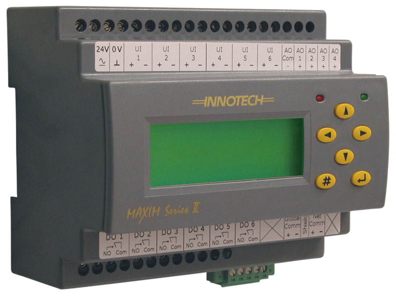
Maxim II (Discontinued)
The MAXIM II Controller is a state of the art digital processing system that has the capability of controlling various types of industrial, commercial and domestic systems. The MAXIM II can operate as a standalone device, using its own universal inputs and analogue and digital outputs to receive information and control external equipment, or as part of a network of devices that support Global NetComms.
*Although these products are no longer available for sale, they are still being supported by Technical Services and Support.List of Benefits
- 100 millisecond cycle/scan time
- 6 configurable universal inputs
- 6 digital relay outputs
- 4 analogue outputs
- User interface on a 4 line, 20 character LCD Display
- 25 user defined watches
MAXIM II Controllers are designed for mounting inside a control cubicle and offers a varierty of inputs and outputs enabling it to monitor and control all types of external plant and equipment. Although the MAXIM II is flexible, it is primarily designed for the air conditioning and building automation industry. The small size of the MAXIM II also gives it the advantage of being fitted in small places without taking up valuable switchboard real-estate.
The MAXIM II's configuration program is developed on a computer using a Windows based program. This allows the user to configure the internal processes of the MAXIM II by using a graphical programming tool. The user places various process blocks and interconnecting lines to design the required control algorithm for the system.
A connector on the bottom right side of the case provides an RS485 serial link to the computer via a 485/232 converter for downloading the configuration program. This link may also be used to upload logged data or the program back out of the controller for modification or debugging purposes.
Key Features
- Data logging of 512 k bytes, approx. 50,000 readings
- Status of I/O points displayed LCD
- 1 RS485 serial communications port for Net Comms
- 1 RS485 serial communications port for Global Comms
- User Selectable Baud Rates:
- Net 9600 Globals 4800 OR
- Net 57600 Globals 38400
- All wire connections by 2.5mm screw terminals
- Program resides in non-volatile Flash Ram
- Real Time Clock, battery backed for approximately 5 years
Applications
- Air conditioning and heating systems
- Lighting control
- Time clock controller
- Monitoring device
- Distributed I/O points controller
- Cold/Freezer Rooms
Approvals
- EN 55011 Class B Group 1& EN 50082-1for CE Marking
- AS/NZS 2064:1997 for C-Tick Labelling.
- Title 47 CFR, Part 15 Class A for FCC Marking
- UL listed to UL916, File Number E242628
| Specification | Detail Description |
|---|---|
| Power Supply | 24VAC ± 10% @ 50/60 Hz., 24VDC ± 10%., Transformer nominal rating of 5VA. |
| Temperature Ratings | Storage 0 to 50°C non-condensing., Operating 0 to 40°C non-condensing. |
| Inputs | 6 Universal Inputs, configurable via software to either |
| Outputs | 6 Digital Outputs:6 x normally open relays (2 amp @ 24VAC), Recomended use of pilot relays when switching high voltage/inductive loads, 4 Analogue Outputs: Analogue Outputs 1 and 2 can be configured individually as either linear 0-10VDC or PWM outputs, Analogue Outputs 3 and 4 are dedicated linear 0-10VDC outputs, Output Load > 2kOhms |
| Battery | Type CR-2032 Lithium, Nominal voltage 3 Volts, Shelf life ~5 Years, dependant on ambient temperature |
| Enclosure | Rectangular case made from flame retardant polycarbonate/ABS plastic listed under UL94 |
| Dimensions (max) | 107mm(w) x 89mm(h) x 69mm(d) |
| Data Logging | Data Logging can be assigned to hardware and software points, Approximately 50,000 time stamped readings 512 kilobyte non-volatile flash RAM, All logged data points can be extracted by using the MAXtract Software tool |
| Communications | RS485 |
MaximII-Datasheet.pdf 906.54 KB
Manual - Current versions
Maxim-System-Manual.pdf 1023.12 KB
Application Notes
GTA-65-Application-Note-1.pdf 736.04 KB

