
4100R
Dual Processor Controller Card
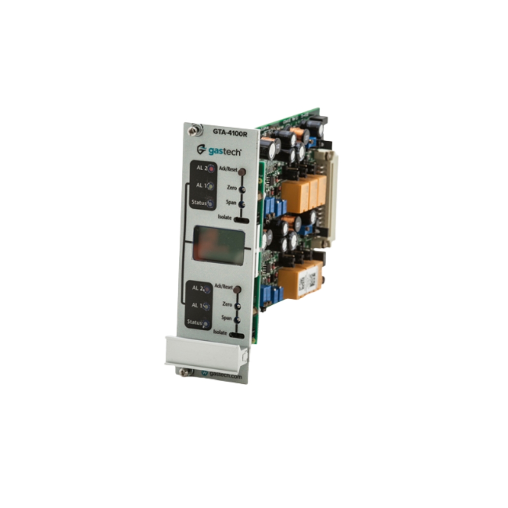
The 4100R is Gastech’s own dual channel gas detection controller card, designed around what happens when something fails. Each channel runs its own processor, so a processor failure costs one channel rather than the panel. The only shared component is the display, and it is non-critical, so both channels keep working even if it dies. Channel isolate takes a point offline for calibration without triggering a shutdown, and cards are hot swap compliant. Universal inputs accept signals from most field devices.
KEY BENEFITS
- Two channels per card with one processor each, so a processor failure costs one channel not both
- The only shared component is the display, and it is non-critical, so both channels keep running
- Dual write display shows both channels at once and keeps working if one processor fails
- Universal inputs accept 4 to 20 mA, voltage, digital and resistance signals from most field devices
- Hot swap compliant, so a card can be changed without shutting the panel down
+ more in the Description tab below
Designed Around What Happens When It Fails
Most controller specifications describe what a product does when it works. The more important question on a safety system is what it does when part of it doesn’t.
The 4100R was specified from customer requirements rather than a feature list: a simple dual channel card with a high level of reliability. One processor per channel. Minimal shared components. Minimal training to commission and calibrate. Minimal add on options to complicate things.
That sounds like a modest brief. In practice, it led to a set of design decisions, each one about making sure a failure doesn’t take the system down with it.
One Processor Per Channel
The card carries two channels and two processors, one per channel, on two separate circuits.
If a processor fails, only one channel is affected. The other keeps monitoring, keeps its alarms live and keeps driving its analogue output. On a panel protecting people, that’s the difference between losing one detection point and losing a zone.
Minimal shared components is why it works. The fewer parts two channels have in common, the fewer single points of failure there are between them.
A Display That Fails Safely
The one component the two channels share is the high resolution graphical LCD, and it was chosen deliberately.
The display has a dual write feature, so both processors write to it at the same time. The top half shows the top channel and the bottom half shows the bottom channel. If one processor fails, the display keeps showing the channel that’s still working.
More importantly, the display is a non critical component and doesn’t influence operation. If it fails completely, both channels still operate correctly. You lose the ability to read the panel, not the panel’s ability to protect the plant.
Isolate, Done Properly
This part is worth reading even if you skip the rest.
Taking a channel offline for calibration is routine. The isolate feature does it without triggering alarms or a shutdown, and the analogue output drops to 1.5 mA, so the control system can see the channel is out of service rather than reading zero.
The operator sees an inverted LCD for that channel, which still shows the current reading. So an isolated channel is clearly marked, and still informative.
There’s also deliberately no isolate timeout.
The reasoning matters. This card is built to drive critical actions, including shutdowns and deluge. If a channel timed out partway through calibration, the isolate would release while gas was still being applied, and an unwanted shutdown or deluge could go off. A timeout meant as a safety feature would become the cause of the incident.
The other half of the reasoning is longer term. A channel under maintenance for weeks keeps showing that it’s offline. Simply switching a channel off isn’t an acceptable substitute, because a fault with no indication on the panel may never get fixed. Someone has to keep seeing it.
Hot Swap
Cards are hot swap compliant, so a faulty card can be replaced without powering down the panel.
On a multi channel system, that matters. Shutting down a panel to change one card means all the other channels on it stop monitoring, which on a live plant means either accepting the exposure or arranging a shutdown window.
Universal Inputs
Each channel accepts a wide range of field signals, which lets one card type serve a mixed site.
Analogue inputs cover 1.4 to 24 VDC and 4-20 mA, source or sink, two or three wire. An internal amplifier means 3 wire catalytic sensors connect directly, along with 0 to 1 V, 0 to 5 V, 0 to 10 V and 0 to 24 V inputs, 24 V digital and resistance inputs.
Setup is by switches on the card, with a graphical guide to the settings printed on the board. That keeps setup documentation to a minimum, and a technician can work out an unfamiliar card in front of them rather than hunting for a manual.
Range is adjustable to 2000, and the display reads in %LEL, ppm, % volume, PPMm, LELm or blank.
Alarms and Relays
Each channel has two alarms and a fault alarm. The low and high alarms are independently adjustable from below zero to full scale, give audible and visual indication, can be acknowledged, and can be set to activate on a rising or falling level.
Falling level activation is what lets oxygen depletion monitoring run on the same card as flammable gas detection.
Each channel has individual relays for low alarm, high alarm and fault, each programmable as latching or non latching, and rated 1 A at 24 VDC. Common relays for low alarm, high alarm and fault are rated 5 A at 24 VDC.
Accept and reset can be local to one channel, or global across the panel.
The Common Module
A common module synchronises all the cards in a panel, so alarm LEDs flash together rather than at random. It’s cosmetic, but it makes a multi card panel easy to read at a glance.
It also holds the panel buzzer and the common relays. And it can zone the top channels of all cards together and the bottom channels together, giving two independent common alarm groups from one panel. That’s useful where one panel covers two areas that need different responses.
Mounting
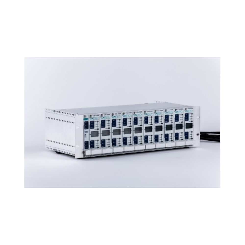
One card, four ways to install it: half rack, full 19 inch rack, panel mount, or an optional NEMA 4X wall mount enclosure.
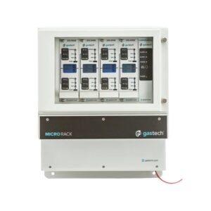
The card is 3U high and 8E wide, at 41 x 173 x 240 mm and 200 grams, so a full 19 inch rack holds a large channel count. For smaller systems, the MicroRack takes the same card in a compact enclosure, for one to eight channels.
The area classification is general purpose. For a classified area, the detectors carry the certification, and the panel sits in a safe area.
Where It’s Used
Gas detection panels in switchrooms and control rooms, multi channel fixed detection systems, mineral processing and surface plant, wastewater treatment works, landfill gas systems, chemical manufacturing, power generation, cold stores and refrigeration plant rooms, carpark and building ventilation control, systems driving shutdown or deluge action, and retrofits replacing older controller cards in existing racks.
Benefits
- Two channels per card with one processor each, so a processor failure costs one channel not both
- The only shared component is the display, and it is non-critical, so both channels keep running
- Dual write display shows both channels at once and keeps working if one processor fails
- Universal inputs accept 4 to 20 mA, voltage, digital and resistance signals from most field devices
- Hot swap compliant, so a card can be changed without shutting the panel down
- Channel isolate takes a point offline for calibration without triggering alarms or a shutdown
- No isolate timeout, so a calibration cannot be interrupted into an unwanted shutdown
- Inverted display shows a channel is isolated while still reading, so nothing sits silently offline
- Two alarms and a fault relay per channel, each programmable as latching or non-latching
- Graphical settings guide printed on the board, so setup needs the card rather than the manual
Channels per card
Two, with one processor per channel
Range
Adjustable to 2000. Reads percent LEL, ppm, percent volume, PPMm, LELm or blank
Inputs
Two 1.4 to 24 V DC, 4 to 20 mA analogue signal inputs, source or sink, two or three wire. Also 3 wire catalytic, 0 to 1 V, 0 to 5 V, 0 to 10 V, 0 to 24 V, 24 V digital and resistance
Analogue outputs
One 4 to 20 mA source per channel, 1,000 ohm maximum impedance at 24 V DC input
Individual relay outputs
Low alarm, high alarm and fault per channel. Programmable latching or non-latching. Each rated 1 A at 24 V DC
Common relay outputs
Low alarm, high alarm and fault. Each rated 5 A at 24 V DC
Low alarm
Independently adjustable from below zero to full scale. Audible and visual indication. Can be acknowledged. Activates on a rising or falling level
High alarm
Independently adjustable from below zero to full scale. Audible and visual indication. Can be acknowledged. Activates on a rising or falling level
Internal amplifier
Yes. Allows direct connection of 3 wire catalytic sensors
Accept and reset
Local to a channel or global across the panel
Channel isolate
Indicated by an inverted display, with 1.5 mA on the analogue output. No timeout
Display
Backlit high resolution graphical LCD per channel, with dual write so both processors write simultaneously
Hot swap
Compliant
Operating voltage
18 to 30 V DC, 24 V DC nominal
Power consumption
0.75 A per channel maximum, fused at 1 A
Operating temperature
Minus 20°C to plus 55°C
Operating humidity
0 to 95%, non-condensing
Rack height
3U
Rack width
8E
Mounting options
Half rack, full 19 inch rack, panel mount, optional NEMA 4X wall mount
Weight
200 g
Overall dimensions
41 mm wide x 173 mm high x 240 mm deep
Area classification
General purpose
Warranty
Two years, materials and workmanship
- Aviation & Transportation
- Carpark & HVAC
- Chemical Manufacturing
- Confined Space & Compliance
- Energy (Oil & Gas)
- Food & Beverage
- Landfill & Remediation
- Marine & Maritime
- Medical & Healthcare
- Mining & Minerals
- Power Generation & BESS
- Technology & Semiconductor
- Water & Wastewater
Only that channel is affected, because each channel runs its own processor on its own circuit. The other channel keeps monitoring and keeps its alarms live.
Both channels keep operating correctly, because the display is a non-critical component that does not influence operation.
Yes, channel isolate takes it offline without actuating alarms or shutdown, drops the analogue output to 1.5 mA and inverts the display so the isolated state is obvious.
Because the card is designed to drive critical action. A timeout releasing mid-calibration could trigger an unwanted shutdown or deluge, and a long term isolate needs to stay visible on the panel.
Yes, the cards are hot swap compliant, so other channels keep monitoring while one card is changed.
Most of them. Inputs cover 4 to 20 mA source or sink, three wire catalytic, 0 to 1 V through 0 to 24 V, 24 V digital and resistance.
Trusted by









Contact Us
Can’t find what you’re looking for? Our team is happy to help.